RED User Guide
While some is universal, much of RED's functionality is broken up into 6 modes - Brush Mode, Face Mode, Vertex Mode, Texture Mode, Object Mode, and Group Mode.
Universal Functions
Hotkeys
Camera Control
View Ports
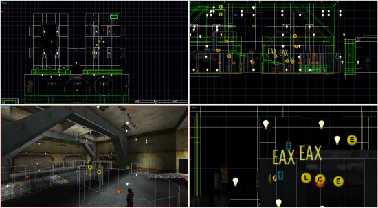
The main portion of Red's interface is divided into four view ports. The view ports are how you see and interact with the world in Red. Each of the view ports is identical and can have any view assigned to it but at least one view port must be assigned to Free Look. You could, for example, have 4 Free Look view ports if you wished. This would, however, take a bit if CPU power to render. You can select a view port to be active by simply moving your mouse over it. There will be a red line on the outer edges of the view port to show it is active. You can "solo" any view port by moving your mouse over it and press "F4". This will stop rendering all the other view ports. You can "un-solo" and set all view ports to their default size by press "F5". The view ports can be arbitrarily resized by moving the center of the view port frame.
There are 2 types of views - Free Look and Orthographic. Free Look is the 3D view of the world and you can move in any direction. in this view. An Orthographic view is a wire frame view of the world and you can only move in 2 axes. The default are (clockwise from upper left) Top, Left, Front and Free Look. Right clicking over the view port's name (in the upper left corner) will bring up view port pop-up menu with the following options:
- View Select: This allows you to assign a view to the view port you are currently in.
- Show Grid: This toggles the grid on or off in that view port. The grid settings under General Preferences overrides this setting.
- Show Links: This toggles object links on or off in that view port. This will show all links between all objects whether they are selected or not.
Status Window/Console
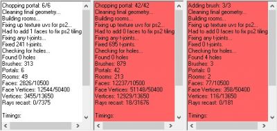
In Red, the status window displays information output by the editor. When you select a brush in brush mode, it's dimensions, UID and time index are displayed here and when you select and object, it's UID and script name are displayed in this window. When you build your level, geometry statistics are printed to the RED status window. If your level has holes or is in excess of the RED geometry limits, the status window will turn red to indicate this.
Toolbar
Across the top of the RED window sit the following toolbar options:
- Mode: This menu selects between Brush, Face, Vertex, Texture, Object or Group mode.
- Coordinates: This menu selects global and local coordinates. Global coordinates are based upon the world axis. Local coordinates are based upon the axis of the currently selected brush or object. Default is global.
- Grid: This menu changes the increment you can move brushes or objects. Default is 1.00.
- Rotate By: This menu changes the increment you can rotate brushes or objects. Default is 15°.
- Camera Speed: This menu changes the speed the camera moves at. Default is 10.
Additionally, the following options are available in the Dash Faction and Pure Faction versions of RED.
- Save: Save the level.
- Pack: Create a level packfile.
- Lighting: Calculate lightmaps and lighting.
- Play: Play level in single player mode from player start. (NOTE: Save and create a packfile before you click this button)
- Play (camera): Play level in single player mode from the current free look view port camera position. (NOTE: Save and create a packfile before you click this button)
Menus
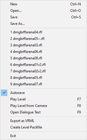
File Menu
- New: Creates a new level file.
- Open: Open a level.
- Save: Save the current level file.
- Save As: Save the current file with a new file name.
- Recently Loaded Files: Lists the 9 most recently open level files.
- Auto-Save: Toggle Auto-Save function.
- Play Level: Play level from player start point.
- Play Level From Camera: Play level from your current camera location.
- Open Dialogue Text: Opens level's text table file
- Export as VRML: Export level in VRML format. Used for importing level geometry into programs like Max, Lightwave, etc.
- Create Level Pack file: Generates pack file (.VPP) for level. You have to create a Level Pack File in order to play your level.
- Exit: Closes editor.
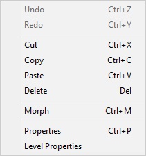
Edit Menu
- Undo: Undo previous operation. The max number of operations you can undo is 16. When you save a level, the undo buffer is cleared.
- Redo: Redo previous operation.
- Cut: Cut currently selected brush(es) and/or object(s).
- Copy: Copy currently selected brush(es) and/or object(s).
- Paste: Paste currently selected brush(es) and/or object(s).
- Delete: Delete currently selected brush(es) and/or object(s).
- Morph: This allows you to change the type of a selected entity, item or clutter object. This can also be done through the object's Property dialog box.
- Properties: This brings up the property dialog box for the currently selected brush(es) or object(s). You cannot see properties for brushes and objects at the same time. You cannot see properties for multiple objects that are not the same type.
- Level Properties: This brings up the Level Properties dialog box.
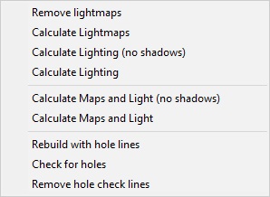
Level Menu
- Remove lightmaps: Remove all lightmaps from the level.
- Calculate Lightmaps: Recalculate lightmaps for the level.
- Calculate Lighting (no shadows): Recalculate lighting without shadows for the level.
- Calculate Lighting: Recalculate lighting for the level.
- Calculate Maps and Light (no shadows): Recalculate lightmaps and lighting without shadows for the level.
- Calculate Maps and Light: Recalculate lightmaps and lighting with shadows for the level.
- Rebuild with hole lines: Always check for Holes after Building the level.
- Check for holes: Check levels for Holes.
- Remove hole check lines: Removes all Hole check lines.
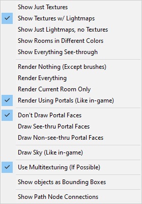
View Menu
- Show Just Textures: Renders level without lightmaps but displays textures.
- Show Textures w/Lightmaps: Render level with lightmaps and textures.
- Show Just Lightmaps, no Textures: Render level with lightmaps and don't show textures.
- Show Rooms in Different Colors: Renders rooms in different colors.
- Show Everything See-through: Render level in wire frame view.
- Render Nothing: Turn off rendering anything.
- Render Everything: Set this flag so you will set a green tint on selected faces which makes texturing much easier.
- Render Current Room Only: This helps you make sure that any Portals you have placed are working correctly.
- Don't Draw Portal Faces: Not implemented.
- Draw See-thru Portal Faces: Not implemented.
- Draw Non-see-thru Portal Faces: Portal faces are rendered.
- Draw Sky (Like in game): Render level with skybox (if it has one).
- Use Multitexturing (If Possible): Not implemented.
- Show objects as Bounding Boxes: Render all objects as bounding boxes. This can give you a significant increase in rendering speed.
- Show Path Node Connections: This will show connections between selected nav points.
Tools Menu
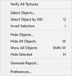
- Verify All Textures: Checks all texture to make sure there are no corrupt bitmaps, that no textures are larger than 256 x 256, and that all textures have dimensions that are a power of 2.
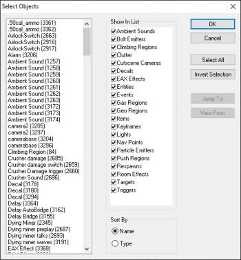
- Select Objects: Brings up the Select Objects dialog box.
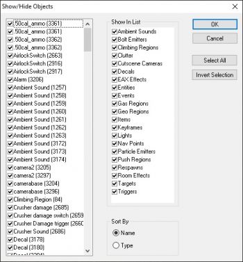
- Hide Objects: Brings up the Hide Objects dialog box.
- Generate Report: Brings up the Generate Report dialog box.
- Preferences: Brings up the Preferences dialog box.
In the Dash Faction version of RED, the following five options are added:
- Select Object by UID: Brings up the Select by UID dialog box. (Hotkey: U)
- Invert Selection: Invert selected objects, brushes, faces, or vertices (depending on mode). (Hotkey: I)
- Hide All Objects: Hide all objects in level. (Hotkey: W)
- Show All Objects: Unhide all hidden objects in level. (Hotkey: Shift + W)
- Hide Selected: Hide all selected brushes and/or objects. (Hotkey: H)
Help Menu
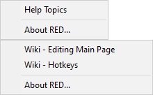
- Help Topics: Brings up RED help file (if available).
- About RED: Displays current version of editor.
In the Dash Faction version of RED, the Help Topics option is removed, and the following two options are added:
- Wiki - Editing Main Page: Open RF1 Editing Main Page in a web browser.
- Wiki - Hotkeys: Open RED Hotkey Reference in a web browser.
Preferences
- Apply: Clicking on this will apply any changes you have made to your preferences to your user config file and exit the preferences dialog box.
- Cancel: Clicking on this will exit the preferences dialog box and you will lose any changes you have made to your preferences.
General Preferences
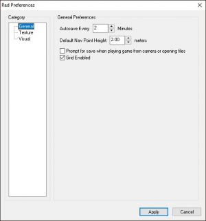
- Auto-Save: Sets the time between auto saves so your level is backed up on a regular basis. A setting of zero will disable auto saving. An Auto-Save .RFL file will have a "~" in the file name.
- Default Navpoint Height: Sets the height at which navpoints are automatically placed above the floor. Default is 2 meters.
- Prompt for save when playing game from camera or opening files: Because of Auto-Save, the editor often "thinks" it has a saved version of your level. If you don't check this flag and go to open a level, the editor will not pop-up a prompt to save the level you are working on.
- Grid Enabled: Turns grid rendering on and off. Does not disable grid snapping with using movement keys.
Texture Preferences
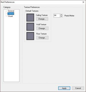
- Default Textures: Set default textures for ceiling, walls and floor. Click "Change" to select a new default texture.
- Change: This button will allow you to browse for textures to use as your default ceiling, wall and floor textures. .
- Pixels/Meter: Sets pixel density. Default is 64. This isn't something you usually change.
Visual Preferences
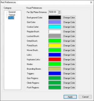
- Far Clip Plane Distance: Sets this distance at which the editor starts rendering in the Free Look Window. Default is 300. Only change this if you are having sorting (Z-buffering) problems in the editor.
- Change Color: Set custom colors for editor rendering. Clicking on "Change Color" will bring up the standard Window palette dialog box.
Mode-Specific Functions
Brush Mode
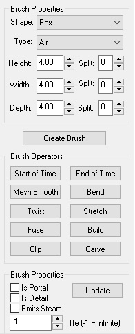
You can use Brush Mode to create and manipulate BSP brushes in your level.
What is a brush?
- See RED Brushes for detailed information on brushes, including types of brushes.
Hotkeys
Properties
- Shape: Change shape of cookie cutter brush. You can select from Box, Cone, Cylinder, Face, Mesh, Sphere and Wedge brushes. You cannot change the shape of a brush after it has been created with this function.
- Type: Set brush material.
- Height: Set height (Y) of cookie cutter brush.
- Height Split: Create evenly spaced vertical segments for the cookie cutter brush.
- Width: Set width of cookie cutter brush.
- Width Split: Create evenly spaced segments for the cookie cutter brush.
- Depth: Set depth of cookie cutter brush.
- Depth Split: Create evenly spaced segments for the cookie cutter brush.
- Create Brush: Creates new brush at the current location of the cookie cutter.
- Is Portal: Sets the brush to act as a Portal.
- Is Detail: Flags the brush to not boolean with the world. See Detail Brushes for more information.
- Emits Steam: Flags the brush to emit steam when shot with an armor piercing round. The brush will only emit 3 steam jets at once. See Steam Emitting Brushes for more information.
- Life: Sets the amount of damage a brush will take before "dying". This is used for Breakable Glass brushes only.
- Update: Updates all flags on the currently selected brush.
Operators
- Start of Time: Moves currently selected brush(es) to the start of time.
- End of Time: Moves currently selected brush(es) to the end of time.
- Mesh Smooth: Applies mesh smoothing to currently selected brush(es). Clicking on this button will bring up the Mesh Smooth dialog box.
- Bend: Bends currently selected brush(es). Clicking on this button will bring up the Bend dialog box.
- Twist: Twists currently selected brush(es). Clicking on this button will bring up the Twist dialog box.
- Stretch: Resize currently selected brush(es) Clicking on this button brings up the Stretch dialog box.
- Fuse: Fuse currently selected brushes.
- Build: Build all unhidden brushes.
- Clip: Brings up the Brush Clipping Tool dialog box.
- Carve: Carve currently selected brushes.
Face Mode
Hotkeys
Operators
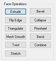
- Extrude - This will take the currently selected face(s) and move it/them a set amount from its/their original position and creates faces to connects them together.
- Bevel - This will bevel the currently selected face(s). Clicking on the button will bring up the Bevel dialog box.
- Flip Edge - Flips the common edge between 2 faces.
- Collapse - This will merge the currently selected faces' vertices at the common point of all their vertices.
- Triangulate - This will select a vertex from the currently selected face(s) and split the face to into triangles that all share a common vertex.
- Pinwheel - Pinwheels the currently selected face(s). Pinwheeling will create a new face for every edge of the currently selected face(s) and create a new vertex at the common center of the new faces.
- Mesh Smooth - Applies mesh smoothing to the currently selected face(s). Clicking on the button will bring up the Mesh Smooth dialog box.
- Bend - Bends 2 or more faces. Clicking on the button will bring up the Bend dialog box.
- Twist - Twist 2 or more faces. Clicking on the button will bring up the Twist dialog box.
- Combine - Combine currently selected faces. You can only combine 2 faces at a time. The faces must be coplanar and be on the same brush. The common vertices of the combined faces will be welded together. If you are combining faces with different textures, the texture of the first face you select will be applied to the second face.
- Stretch - Scale currently selected face(s). Clicking on the button will bring up the Stretch dialog box.
Vertex Mode
Hotkeys
Operators
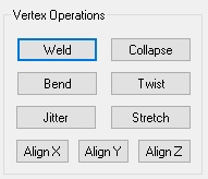
- Weld - This merges one or more vertices to a single vertex. You always merge the first vertex you select to the last vertex you select. You can weld more than 2 vertices at a time but they always merge to the last selected vertex.
- Collapse - This is similar to welding but it merges vertices to the average point between them.
- Bend - Bend the currently selected vertices. Clicking on this button will bring up the Bend dialog box.
- Twist - Twist the currently selected vertices. Clicking on this button will bring up the Twist dialog box.
- Jitter - Jitter the currently selected vertices. Clicking this button will bring up the Jitter dialog box.
- Stretch - Scale 2 or more vertices. Clicking on the button will bring up the Stretch dialog box.
- Align X/Y/Z - This will align 2 or more vertices to a point that is the average distance between them along the selected axis. Please note that aligning vertices does not always snap the vertices to the grid.
Texture Mode
Textures are what you see on the polygons (faces) in a level. Textures are applied to all surfaces of a polygon in RED editor. When calculating/adding lightmaps, another texture map (called a lightmap) is added to each surface of your level (except for "Full Bright" faces). This is done by baked grayscale images which tells the surfaces how illuminated they should be. RED supports Smoothing Groups for the lightmaps to make lighting appear seamless on rounded surfaces.
Hotkeys
Operators
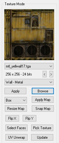
- Currently Selected Texture: Displayed in this window. The size and format are displayed below the name. You can select textures in the current directory from the pull-down list. You can also use the left and right arrow button to scroll through the textures in the current directory. The texture directory can be changed via the pull-down list that is above the Apply and Browse buttons.
- Apply: Apply current texture to all selected faces.
- Browse: Open Texture Browser Window.
- Mapping Types: Select between box, planar, and cylindrical Texture Mapping Types.
- Apply Map: Apply selected Texture Mapping Type to all selected faces.
- Resize Map: Changed diameter and height of cylindrical map.
- Snap Map: Snap cylindrical map to center point of selected brush(es).
- Flip X: Flip mapping coordinates of selected faces horizontally.
- Flip Y: Flip mapping coordinates of selected faces vertically.
- Select Faces: Select all faces with current texture.
- Pick Texture: Make texture of the currently selected face the currently selected texture. If you have more than one face selected and the faces do not all have the same texture, it will use the texture from the first face you selected.
- UV Unwrap: Open UV Unwrapper with selected face(s).
- Update: Refresh all textures. If you modify a texture you currently have loaded, click on this to update the texture and show the changes.
Object Mode
When in Object Mode you can create, place, and perform operators on objects in your level.
What is an object?
- See RED Objects for detailed information on objects, including a list of available object types.
Hotkeys
Operators
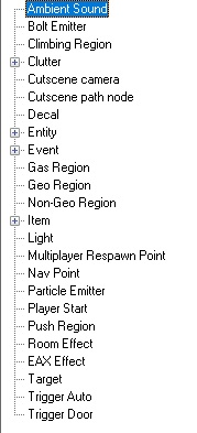
- Object List: This lists all objects and events you can place in a level. Clicking the "+" sign will expand that part of the Object List. The currently selected object is always highlighted and double-clicking on an object in the list will create an object at the current location of your camera with your camera's current orientation.
Group Mode
What is a group?
- See RED Groups for detailed information on groups.
Hotkeys
Operators
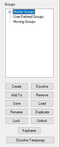
- Groups: This is the group tree. Groups are broken down into three categories. The first is Master Groups which are created by the editor and cannot be modified. Whenever you create anything in the editor, it will be added to a Master Group. The second category, User-Defined Groups, are groups that you create. Using User Defined Groups will make the level design process much easier for you. The last category is reserved for Moving Groups. The currently selected groups will be highlighted in blue.
- Create: Creates a User Defined Group from the currently selected brush(es) and/or object(s). Clicking this button will bring up a dialog box so you can name your new group. If you choose not to name a group, it will be automatically be named "temp###". "Temp" group names are automatically and incrementally named.
- Dissolve: This will dissolve the currently selected group. It will not delete any brush(es) or object(s) in the group.
- Add To: This will add the currently selected brush(es) and/or object(s) to the currently selected group.
- Remove: This will remove the currently selected brush(es) and/or object(s) from the currently selected groups.
- Save: This allows you save out User Defined Group and Moving Groups. This will bring up the Save Group dialog box.
- Load: This will bring up the Load Group dialog box. When you load a group, it will always be placed at the location it was saved at.
- Rename: This will allow you to rename the currently selected group.
- Lock: This will lock all brushes of the currently selected group so they cannot be moved or modified accidentally.
- Unlock: This will unlock all brushes of the currently selected group so they can be moved or modified.
- Duplicate: This will create a duplicate of the currently selected group. The duplicate group will retain all links within itself. You can chose to have the editor automatically rename the duplicate group or change the name manually.
- Keyframe: This will create a keyframe for a Moving Groups or turn a User Defined Group into a Moving Group
- Dissolve Temporary: This will dissolve all temporary User Defined Groups (temp###) that you have created.
Tools
Level Properties
Accessible via Edit Menu
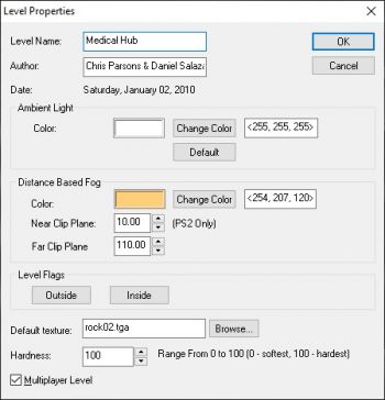
- Level Name: This is the name that will appear when the level first loads.
- Author: Your name goes here.
- Date: The date the level was first created.
- Ambient Light
- Color: This is the minimum light color and brightness that your level will have. Default is 40, 40, 40.
- Change Color: Clicking on this button will bring up the standard Windows palette dialog box to use to select your ambient light value.
- Default: Resets the ambient light values to default.
- Distance Based Fog
- Color: This is the color of level fog.
- Change Color: Clicking on this button will bring up the standard Windows palette dialog box to use to select your fog color. Default is 40, 40, 40
- Near Clip Plane (PS2 Only): This sets the distance at which fogging will start to occur. Please note that this feature was put in the Playstation 2 version of Red Faction and does not work on the PC version of Red Faction.
- Far Clip Plane: This sets the distance at which fog will be opaque.
- Level Flags: These button allow you to flag an entire level as being inside or outside. If a level is flagged as "Outside", the level will considering unpressurized and players will take damage when their armor reaches zero. You can also accomplish this with a Room FX object.
- Default Texture: This is the default texture that is used for geomods.
- Browse: Clicking on this will bring up a dialog box so you can choose a default geomod texture.
- Hardness: This sets how geomods affect the level. Lower values will cause explosions to make bigger holes and higher values will cause explosions to make smaller holes.
- Multiplayer: This flag must be set if you are creating a multiplayer level. If this flag is set, Cutscenes will not work, and Cutscene Camera objects instead will be used for scoreboard camera angles in multiplayer games.
Select Objects
Accessible via Tools Menu
- OK: Click this to confirm any changes you have made and close the dialog box.
- Cancel: Click this to close the dialog box and lose any changes you have made.
- Object List: This shows every object (and it's UID) in the level that is currently not hidden.
- Show In List: This displays all the categories of objects. The checkbox allows to selectively filter out whole categories of objects form the Object List.
- Sort By Name: This will sort the Object List by the script name of the objects.
- Sort By Type: This will sort the Object List by object category.
- Select All: Click this to select all objects currently displayed in the Object List
- Invert Selection: Click this to invert the selection of any objects in the Object List.
- Jump To: Close Select Objects and jump camera in currently active viewport to the XYZ of the selected object.
- View From: Not implemented. Use Teleport (CTRL + T) instead.
Hide Objects
Accessible via Tools Menu
- OK: Click this to confirm any changes you have made and close the dialog box.
- Cancel: Click this to close the dialog box and lose any changes you have made.
- Object List: This shows every object (and it's UID) in the level. The checkbox next to the object indicates whether it is hidden or not.
- Show In List: This displays all the categories of objects. The checkbox allows to selectively filter out whole categories of objects form the Object List.
- Sort By Name: This will sort the Object List by the script name of the objects.
- Sort By Type: This will sort the Object List by object category.
- Select All: Click this to select all objects currently displayed in the Object List
- Invert Selection: Click this to invert the selection of any objects in the Object List.
Generate Report
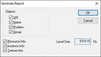
Accessible via Tools Menu
- OK: Generate report with currently selected options.
- Cancel: Close the dialog box.
- Objects: If you want object information included in the generated report, tick the information you want.
- Resource Info: Tick to include resource info in generated report.
- Instance Info: Tick to include instance info in generated report.
- Texture Info: Tick to include texture info in generated report.
Brush Clipping
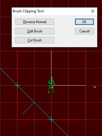
Accessible via Brush Mode
The brush clipping tool allows you to cut or split a brush or brushes along a plane defined by two control points. The plane is indicated in the editor by a blue line. At the line’s center is a small line segment called a normal, which is used to indicate which portion of the brush will be discarded when the brush is cut You must select at least one brush before starting the brush clipping tool. Then place two control points in any of the views (except for the free-look view). To place a control point, simply click where you want the link to be created. The editor will take the control points, align them with the grid, and draw the line between them indicating the clipping plane. Now click on the Split Brush or Cut Brush button to perform the clipping operation.
- Reverse Normal: Click this to change the direction of the clipping plane’s normal. This allows you to cut the opposite portion of the brush(es).
- Split Brush: Click this to split the brush(es) along the clipping plane. This adds faces to the brush in question, which can be very useful in texturing larger brushes.
- Cut Brush: Click this to cut the brush(es) along the clipping plane. The direction of the normal will determine which side of the brush(es) is cut.
- OK: Click this if you want to accept the clipping operation and close the dialog box.
- Cancel: Click this to close the dialog box and lose any changes made by clipping operation..
Fuse
Accessible via Brush Mode
Fusing is used to make 2 or more brushes into 1 brush. While this function is not used that often, it comes in handy in certain situations. Once you fuse brushes together, you cannot "un-fuse" them. You can undo the operation but if the undo buffer gets refreshed and the fuse operation you just performed is gone, you are out of luck. It's a good idea to make a habit of backing up brushes before you fuse them together. The easiest way to make a backup of the brushes is to create a User Defined Group and save the group out. This way, if you need the original separate brushes back, you can just load the group. You can only fuse 2 brushes at a time. If you try to fuse more than 2 brushes at once, faces will disappear. When you fuse brushes together, common vertices are welded together.
To use the Fuse function, simply click on a brush to select it then CTRL + click on the other brush you want to fuse to the first brush. Now click on Fuse, rebuild the level and you're done.
Carve
Accessible via Brush Mode
Carving is used to "permanently" cut one brush with another brush. This is basically how the engine works any way but carving allows you to create a single complex brush that would normally take many brushes to create. Sometimes, this makes managing brushes easier. You can only carve with 2 brushes at a time. If you try to carve with move than 2 brushes at once, faces will disappear. You can only carve a solid brush but it can be carved with either an air or solid brush. The brush that is earliest in time (out of the two) will be the bit that is carved by the second brush, which must be the later in time of the two. The time index of brushes is displayed in the Status Window. Once you carve a brush, you cannot "un-carve" it so it's a good idea to make a backup of the brushes before you carve them. Brushes can only be "uncarved" with Undo but if the undo buffer gets refreshed and the carve operation you just performed is gone, you are out of luck. The easiest way to make a backup of the brushes is to create a group and save the group out.
To use the Carve function, check the time indexes of the two brushes you want to use for carving. If you need to change their times, use the Start of Time and End of Time buttons to move them in time.
If the time indexes of the brushes is all set, then just select both brushes and click carve. Then move or delete the brush you carved with and you will see how the new carved brush looks.
Mesh Smooth
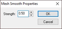
Accessible via Brush Mode or Face Mode
Mesh smoothing is an operation that can be applied to a whole brush mode or select faces Basically it does what it says. It smoothes out a brush or group of faces by adding more faces. Technically, mesh smoothing creates a new face for every the edge and vertex of the selected faces. Mesh smoothing does add more faces so be careful when you use it.
- Strength: This controls the size of the original faces of the brush. Lower values will make the original faces smaller. The default is 0.50.
- OK: Click this to confirm any changes you have made and close the dialog box.
- Cancel: Click this to close the dialog box and lose any changes you have made.
Bend
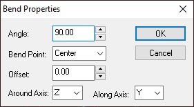
Accessible via Brush Mode, Face Mode, or Vertex Mode
Bend is a very powerful tool that allows you to create curved brushes quickly and easily. To create a curved brush, you have to create a brush that is segmented. You can do this by either splitting the brush when you create it or by extruding faces after you create it.
- Angle: The amount the brush is bent.
- Bend Point: Changes whether the bend occurs around at the beginning, center or end of the brush.
- Offset: This offsets the the bend point by X meters.
- Around Axis: This sets the axis that the brush will bend around.
- Along Axis: This sets the axis that brush will bend along. The will typically be the axis that is the longest dimension of the brush.
- OK: Click this to confirm any changes you have made and close the dialog box.
- Cancel: Click this to close the dialog box and lose any changes you have made.
Twist
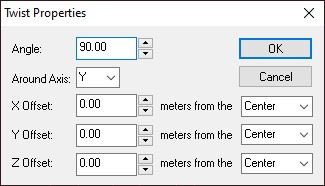
Accessible via Brush Mode, Face Mode, or Vertex Mode
Twist allows you to create very complex curved brushes quickly and easily. Think of Twist as doing multiple bends at once. As with Bend, you have to create a brush that's segmented. You can do this by either splitting the brush when you create it or by extruding faces after you create it.
- Angle: This sets the amount of the twist.
- Around Axis: This sets the axis around which the brush will twist. For best results, always twist around the axis of the longest dimension of the brush
- X/Y/Z Offset: These values will move the center point around which the brush is twisting. By selecting minimum, center or maximum you can easily move the point around which the brush twists without having to adjust the X/Y/Z offset values
- OK: Click this to confirm any changes you have made and close the dialog box.
- Cancel: Click this to close the dialog box and lose any changes you have made.
Stretch
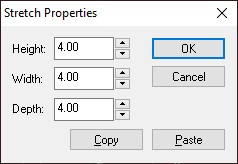
Accessible via Brush Mode, Face Mode, or Vertex Mode
Stretching allows you to change the size of brush, a face or a group of vertices. The stretch dialog is available in brush, face, and vertex. While you can manually move a face or group of vertices to resize a brush, stretching lets you quickly enter precise dimensions.
- Height: You can type the height in or use the up/down buttons to change the current value.
- Width: You can type the width in here or use the up/down buttons to change the current value.
- Depth: You can type the depth in or use the up/down buttons to change the current value.
- OK: Click this to confirm any changes you have made and close the dialog box.
- Cancel: Click this to close the dialog box and lose any changes you have made.
- Copy: This is very handy feature. If you want 2 or more brushes to be the same size, you can use copy and paste to copy one brush's dimensions to another. Simply select the brush you want dimensions from, open the Stretch dialog box, then click Copy. Now select the brush you want to copy the new dimensions to, open the Stretch dialog box for that brush, click on Paste and you're done.
- Paste: See above.
Jitter
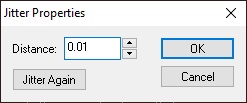
Accessible via Vertex Mode
Jitter allows you to randomly move vertices (within an amount that you define) to create more natural shapes with your brushes.
- Distance: This sets the maximum distance a vertex will randomly move from it's original position.
- Jitter Again: This will move the selected vertices again.
- OK: Click this to confirm any changes you have made and close the dialog box.
- Cancel: Click this to close the dialog box and lose any changes you have made.
Bevel
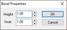
Accessible via Face Mode
- Height: This sets the distance of the beveled face from the original face.
- Inset: This sets the distance that the vertices of the beveled face are moved to (positive values) or from (negative values) the original face.
- OK: Click this to confirm any changes you have made and close the dialog box.
- Cancel: Click this to close the dialog box and lose any changes you have made.
Texture Browser
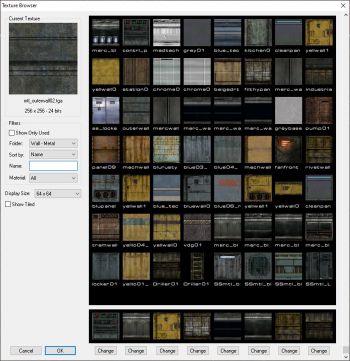
Accessible via Texture Mode
You can use the texture browser to view and select textures to apply to faces in texture mode. The texture browser is also used when selecting a bitmap for a Liquid Room or Decal.
- Current Texture: This displays the texture you currently have selected to apply. The name, size and format are displayed below.
- Show Only Used: This flag will only display textures in the browser that you have used in your level. This really speeds up the time it take to load large directories and helps you find textures you have used much faster.
- Folder: This displays the current texture folder you are browsing. Selecting "All" will display every single texture in the game in the browser window. Please note that, depending on the speed of your computer, this can take quite a while.
- Sort By: You can either sort the textures you are browsing by name or date. Sorting by date makes finding textures you just created or added to Red much faster.
- Name: This allows you search for textures in the current directory by using part of a texture's file name (i.e. mtl_bla). You cannot use wildcards like "*" in your search.
- Material: This allows you to sort the current texture directory by material type. Most directories are only one material type but some like Trim are more than one material type. See RF1 Materials for a list of available materials and their properties.
- Display Size: This changes the sizes of the thumbnails displayed in the browser window.
- Show Tiled: This flag will show the currently selected texture tiled in the main texture browser window. You can also show the currently selected texture tiled by right clicking over the main texture browser window.
- Favorite Textures: This allows you to select up to 8 different textures for quick and easy access. To change a favorite texture, simply double click on it in the main texture browser window then click on the Change button beneath the spot where you want the new favorite texture to be.
- OK: Click this once you have selected the texture you wish to use.
- Cancel: Click this if you wish to exit the texture browser.
UV Unwrapper
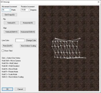
Accessible via Texture Mode
You can use the UV Unwrapper to manually edit UV coordinates of faces for texture projection.
- Movement Increment: Set movement distance with keyboard.
- Rotation Increment: Set rotation amount with keyboard.
- Grid Snap: Snaps all selected vertices to current grid size.
- Flip Vertical: Flips selected vertices vertically.
- Flip Horizontal: Flips selected vertices horizontally.
- Align Vertical: Snaps selected vertices vertically at the average point between them.
- Align Horizontal: Snaps selected vertices horizontally at the average point between them.
- Line Color: Displays current color for unwrapper lines.
- Change Color: Displays standard Windows color palette dialog box.
- Print: Takes screen capture (.tga) of UV unwrapper window. Useful for creating custom fitting textures.
- Non-Uniform Scaling: This allows you precisely scale vertices in both the horizontal (U) and vertical (V) directions. This is very useful for scaling textures on non-rectangular faces.
- Show Tiled: Show the tiling pattern of the texture.
Select by UID
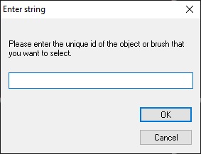
Accessible via Tools Menu, or by U hotkey in Brush Mode, Object Mode, or Group Mode
- UID Input: Provide the UID of the object or brush you wish to select.
- OK: Generate report with currently selected options.
- Cancel: Close the dialog box.
